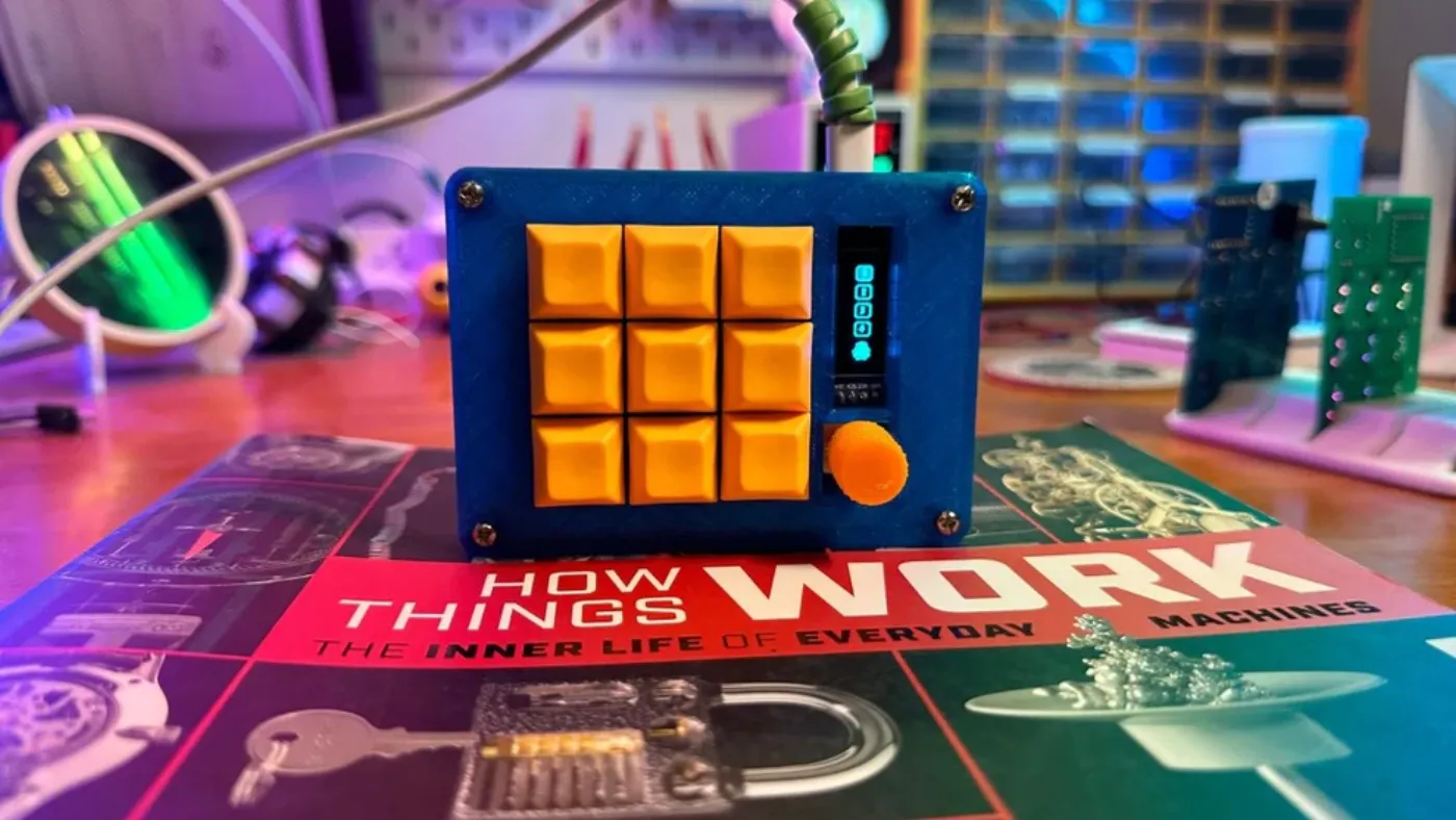
A fully open-source 3x3 QMK macropad with hotswap switches and USB-C. Made in Bengaluru.
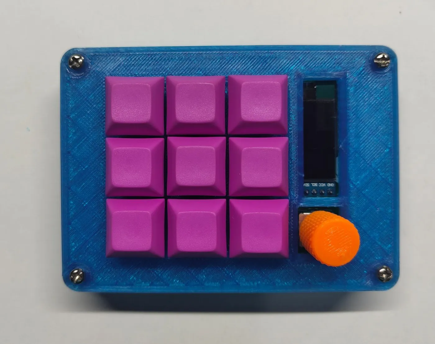
Nine keys, a rotary encoder and up to four layers - in a footprint that sits under your palm.
Click any file to preview it - read the schematic, scan the BOM, then download.
A great first soldering project. Every component is through-hole - no surface-mount work required. Set aside a couple of hours, gather the parts from the inventory list, and follow the steps in order.
You will need: a soldering iron, solder (flux-core recommended), a screwdriver, tweezers, and a pair of pliers. A breadboard is also useful for Step 2.
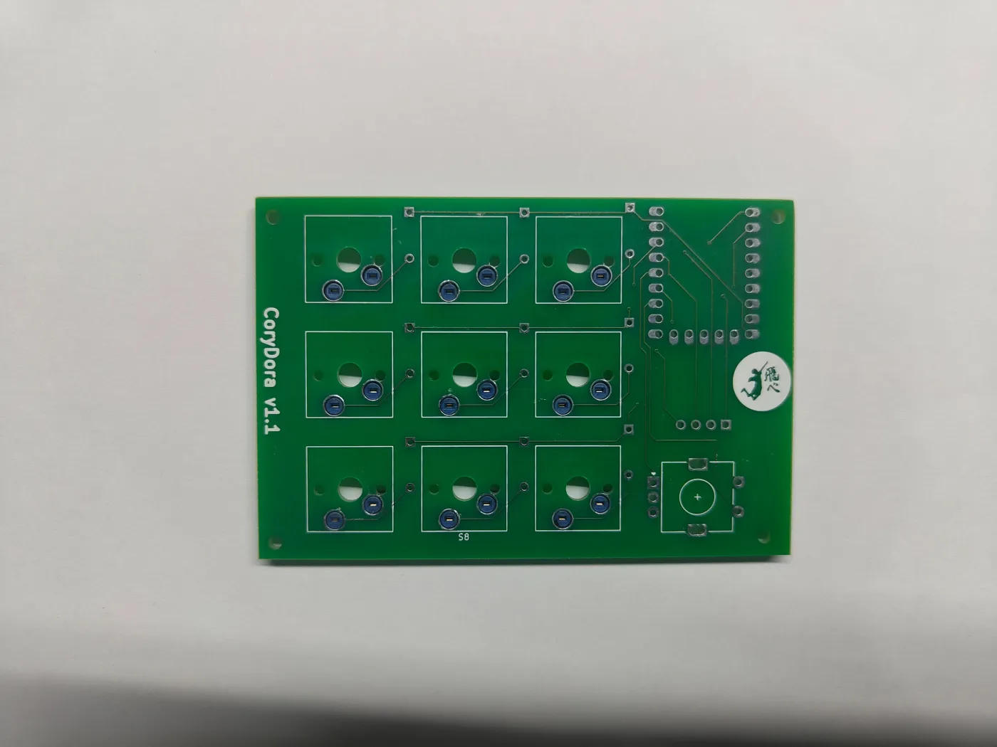
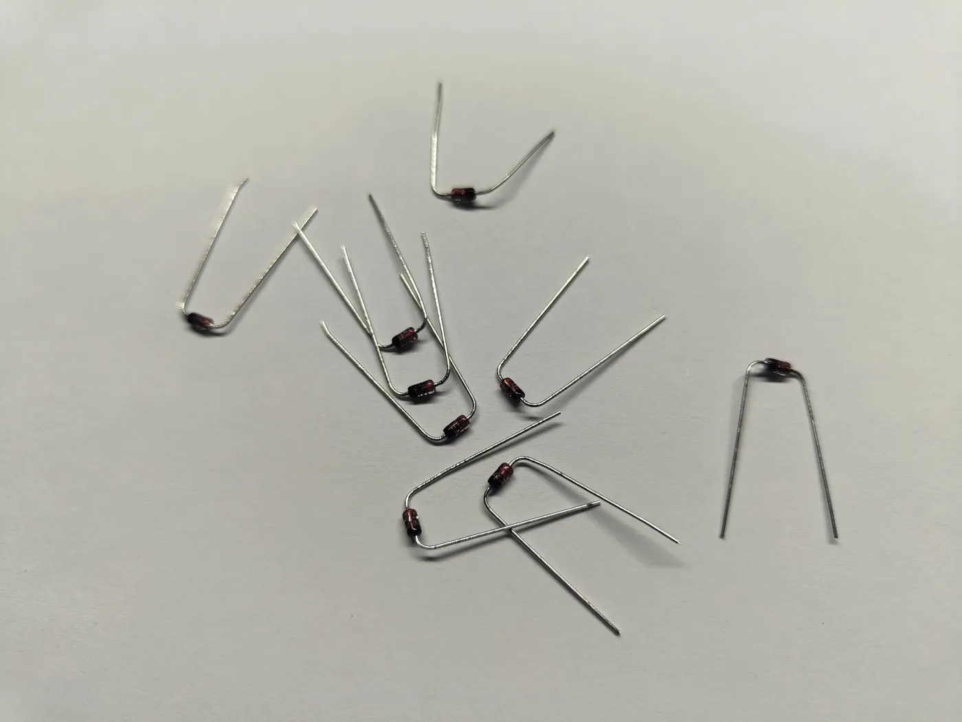
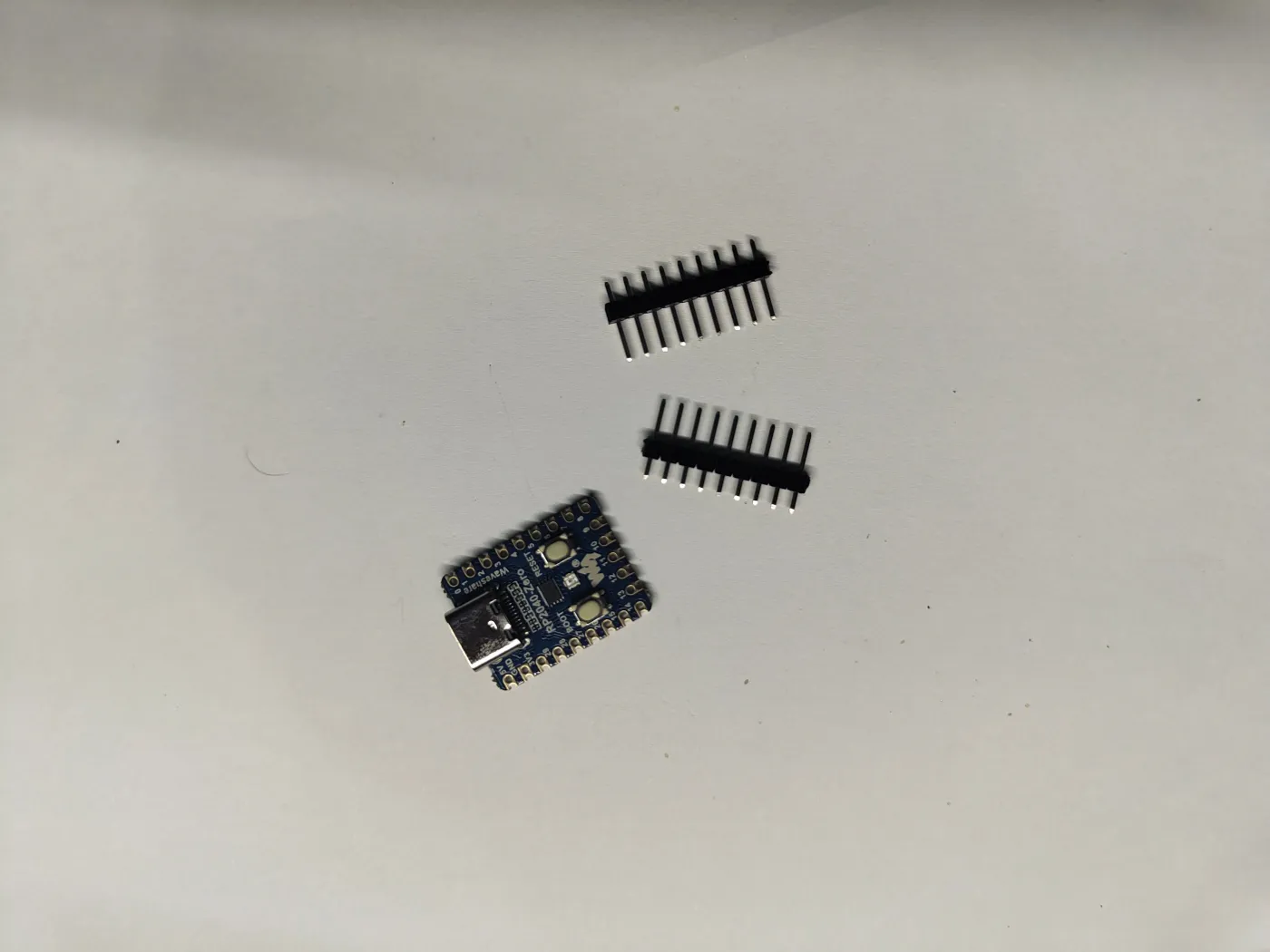
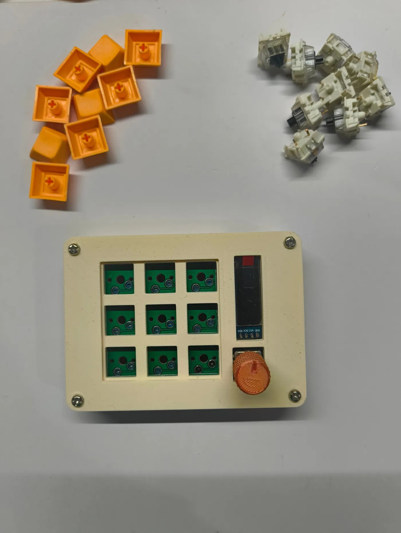
Before starting, lay out all parts: the CoryDora PCB, 9 diodes, RP2040 Zero, rotary encoder, OLED display, 8x M2 and 8x M2.5 screws, and 3D-printed case parts (bottom, top, trim).
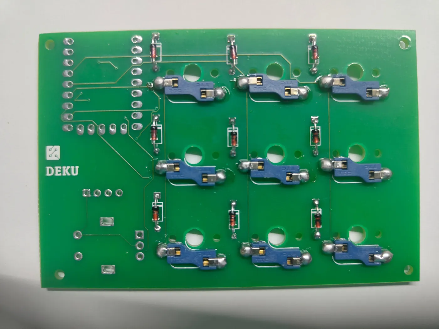
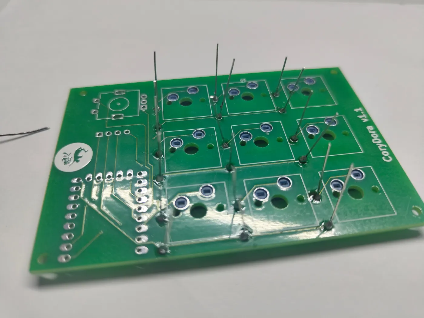
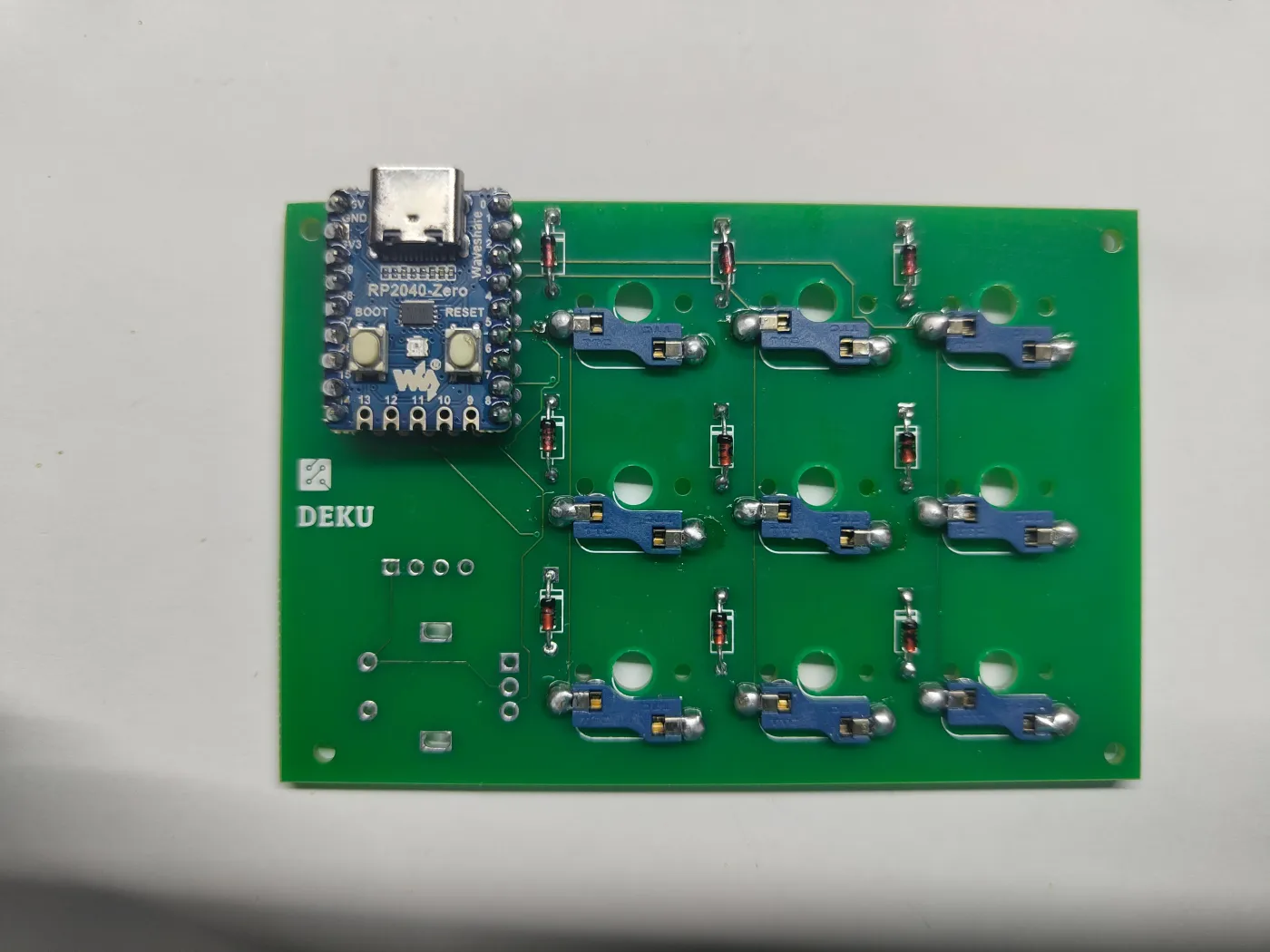
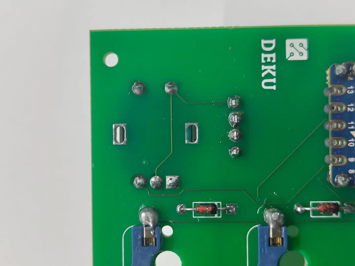
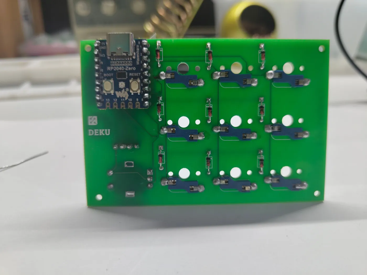
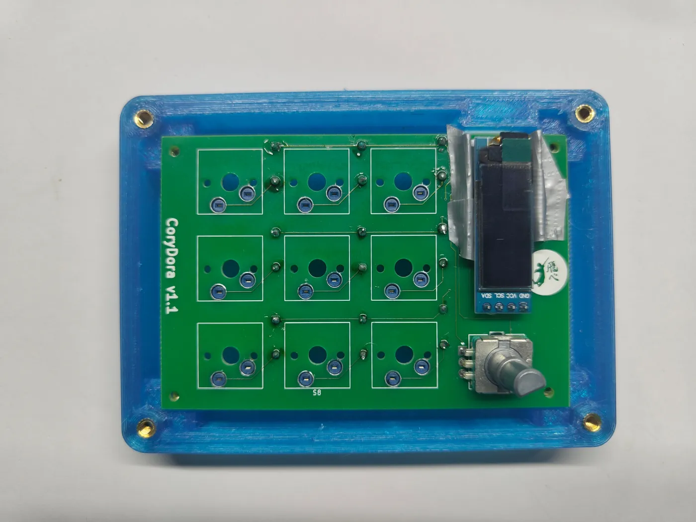
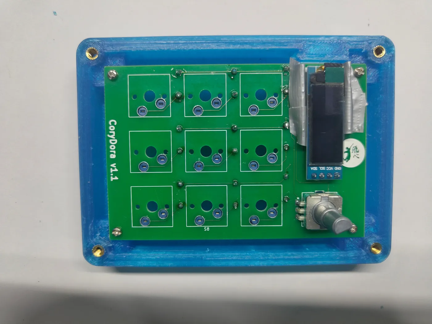
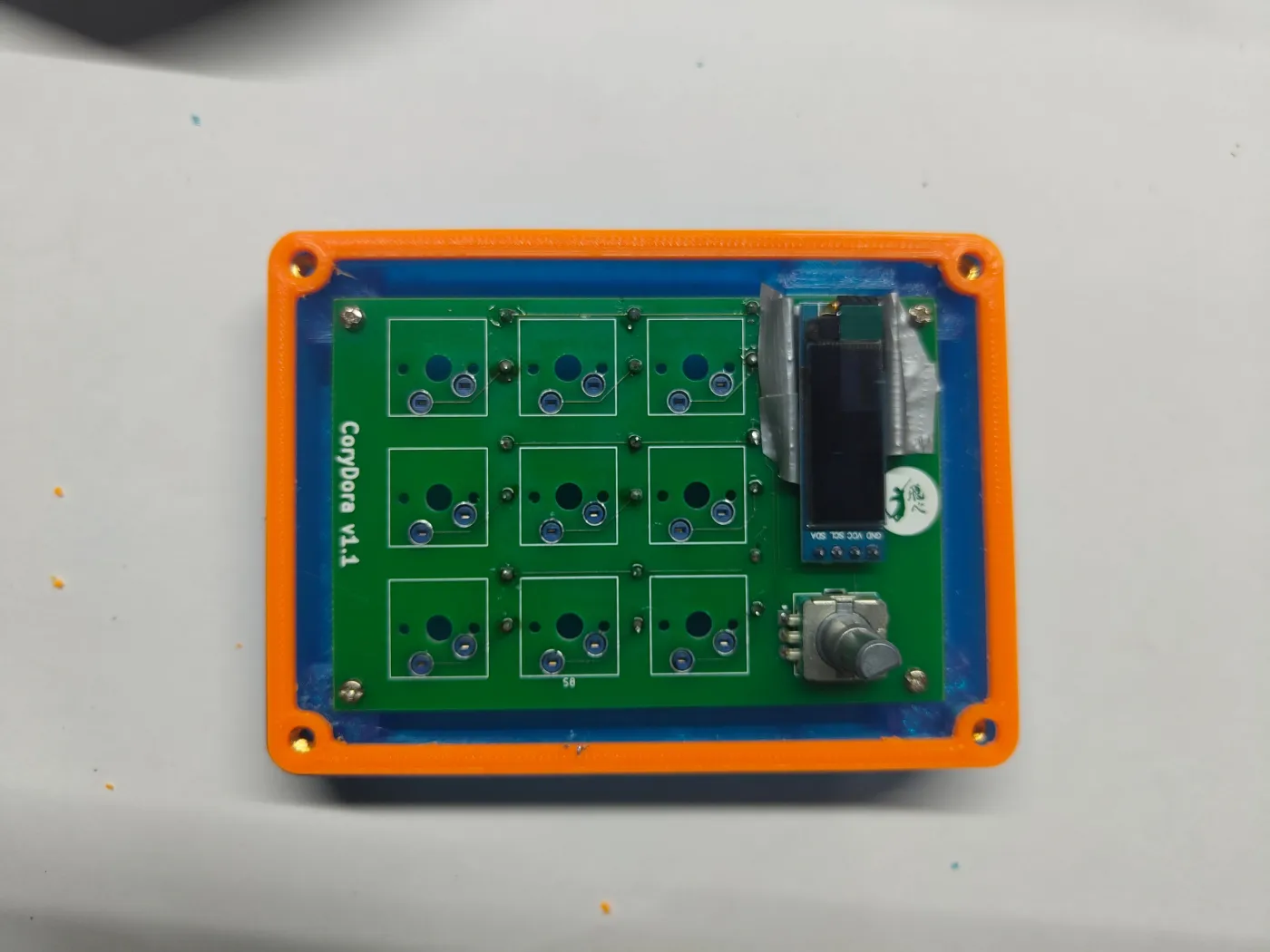
Familiarise yourself with the PCB before soldering. The top side holds the display, encoder, and switch sockets. The bottom side holds the diodes and microcontroller.
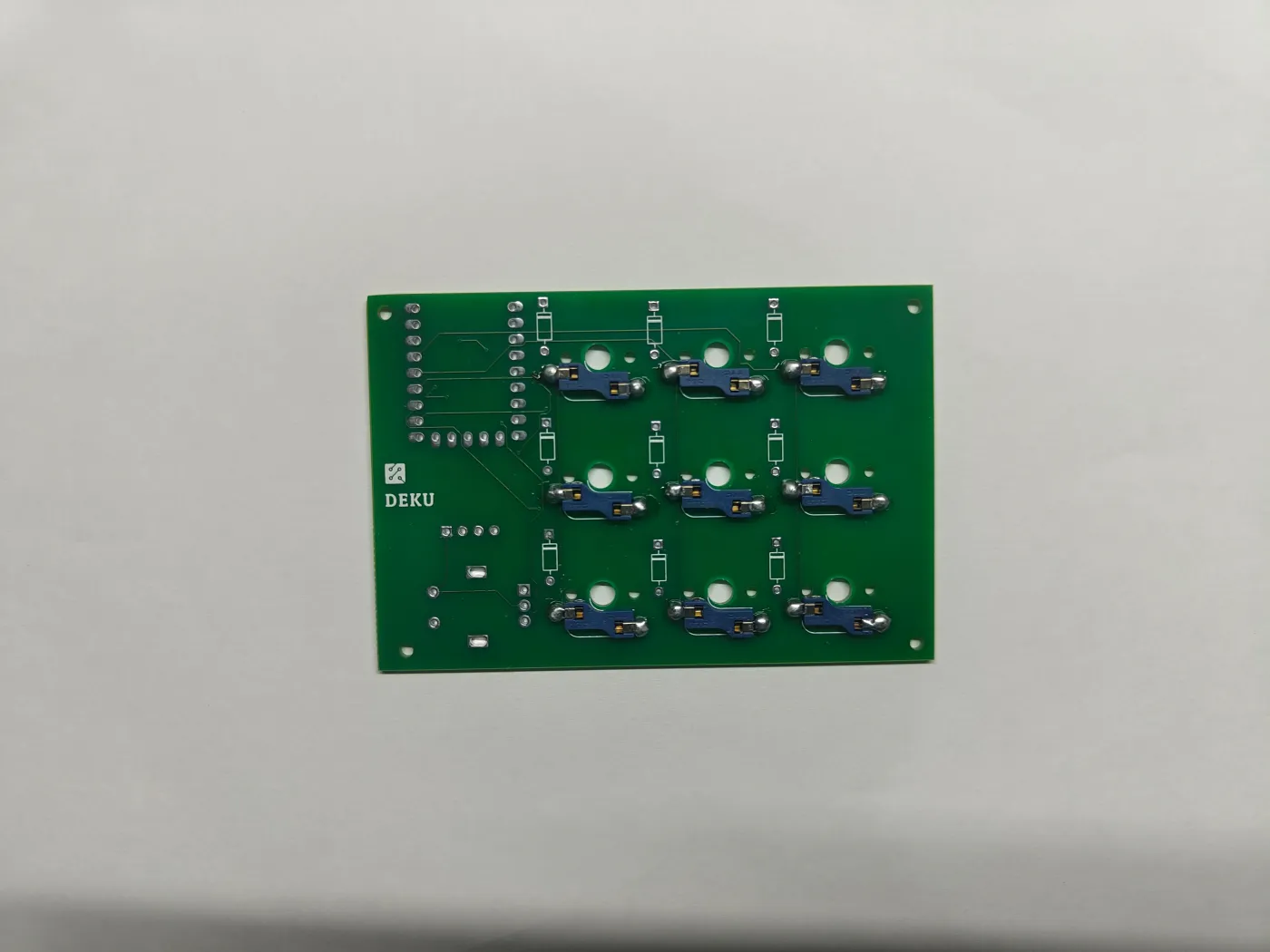
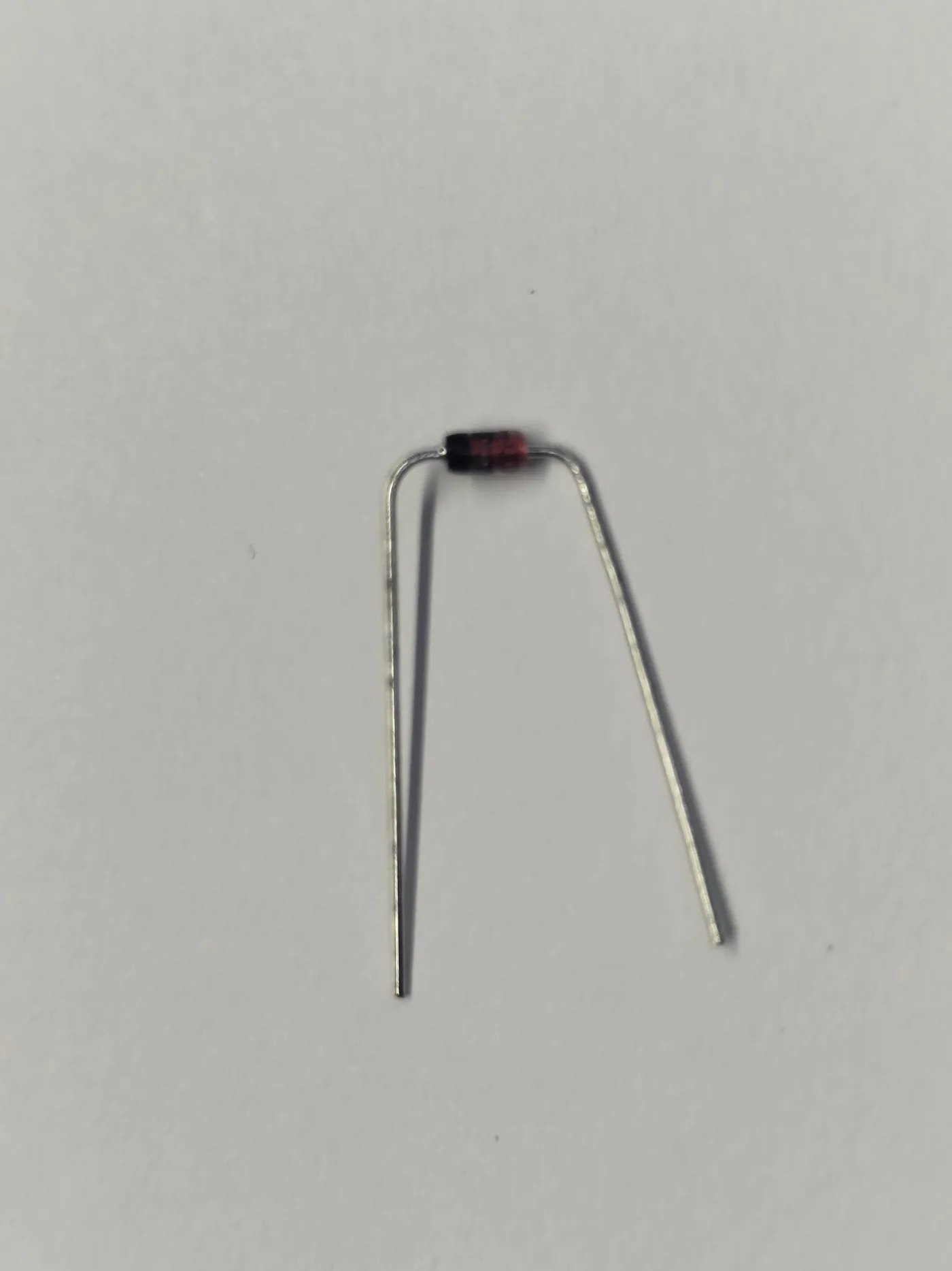
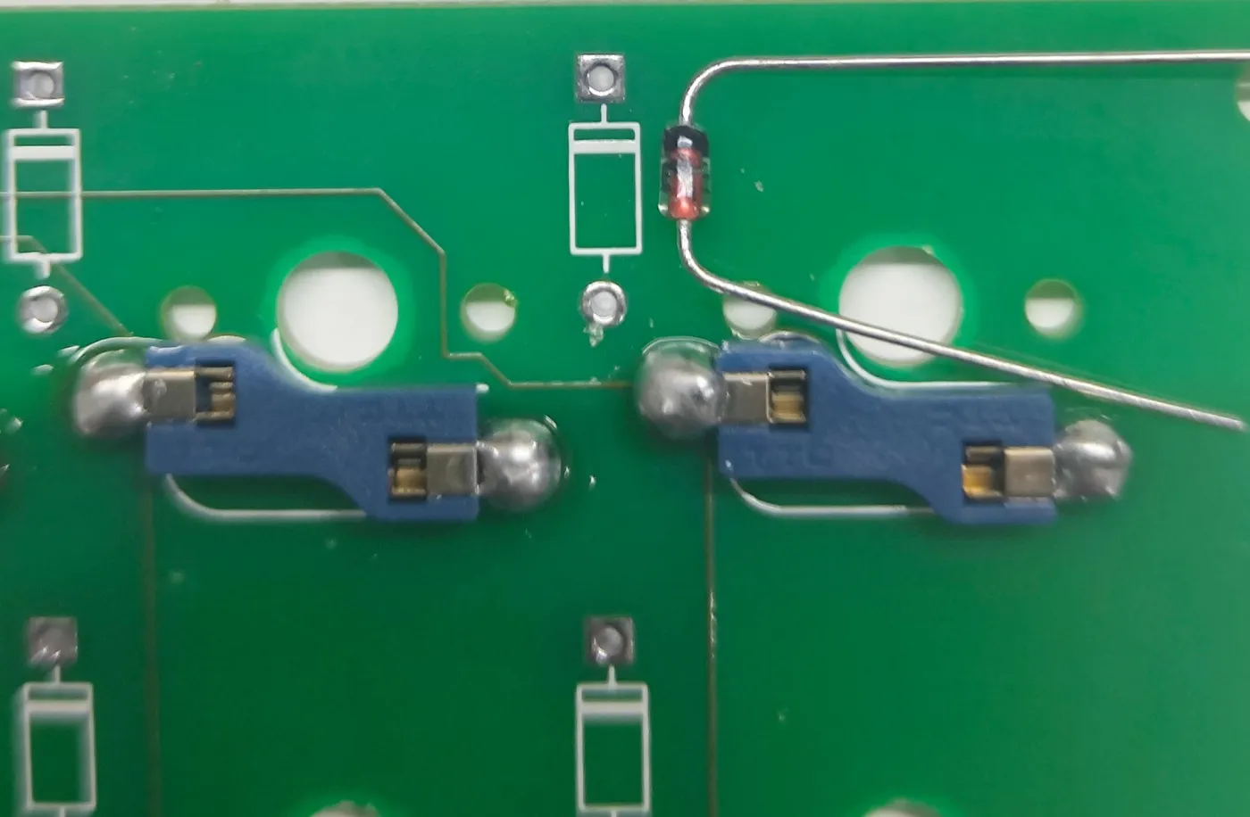
Bend each diode leg at 90 degrees. Every diode has a black stripe on one end - align that stripe with the marking on the PCB silkscreen. Insert all 9, then solder from the top side. Trim the excess leads with pliers.
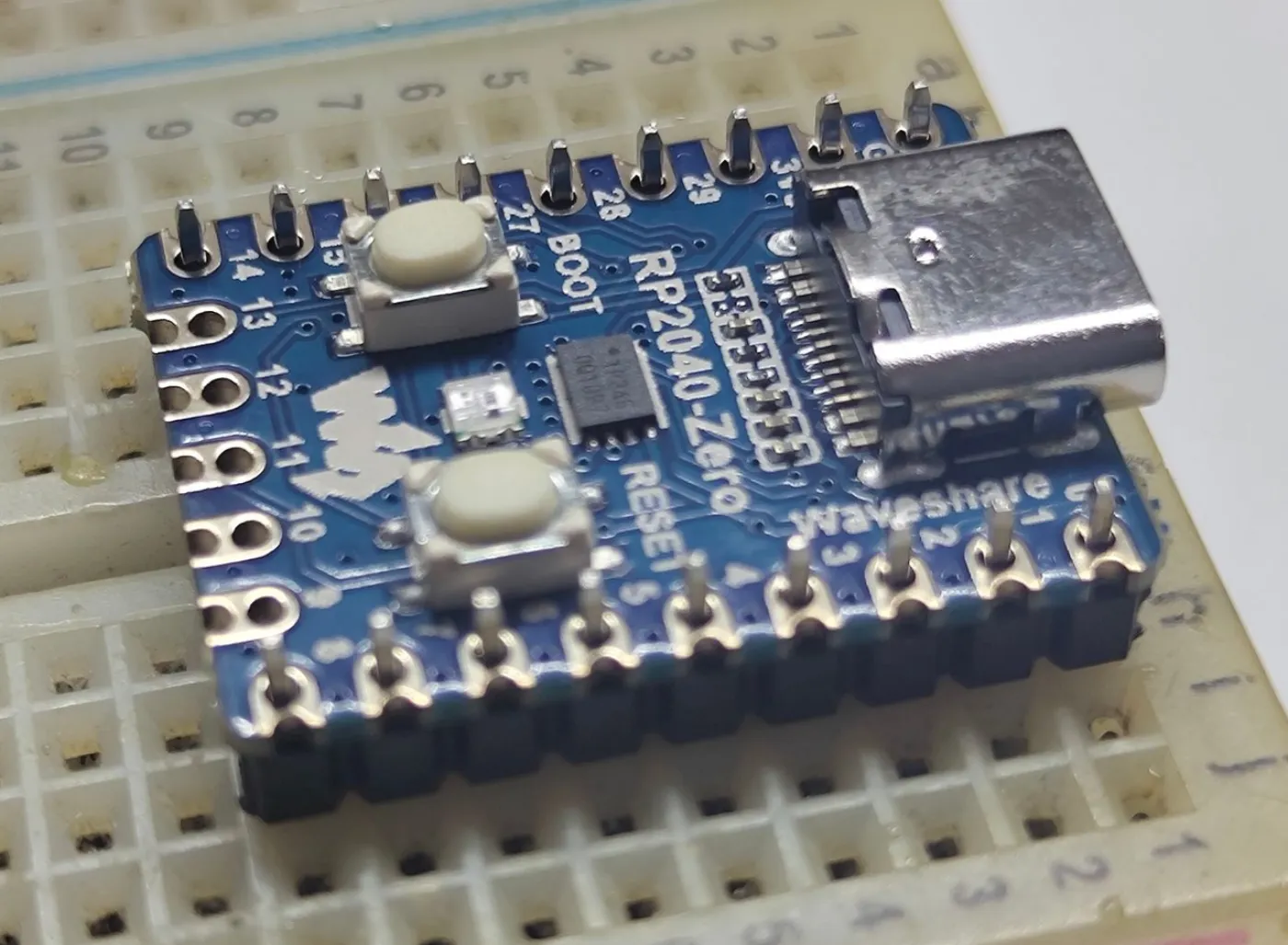
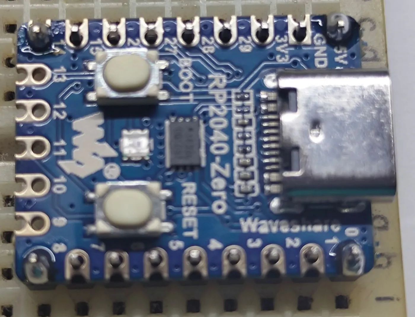
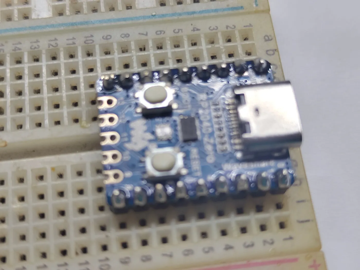
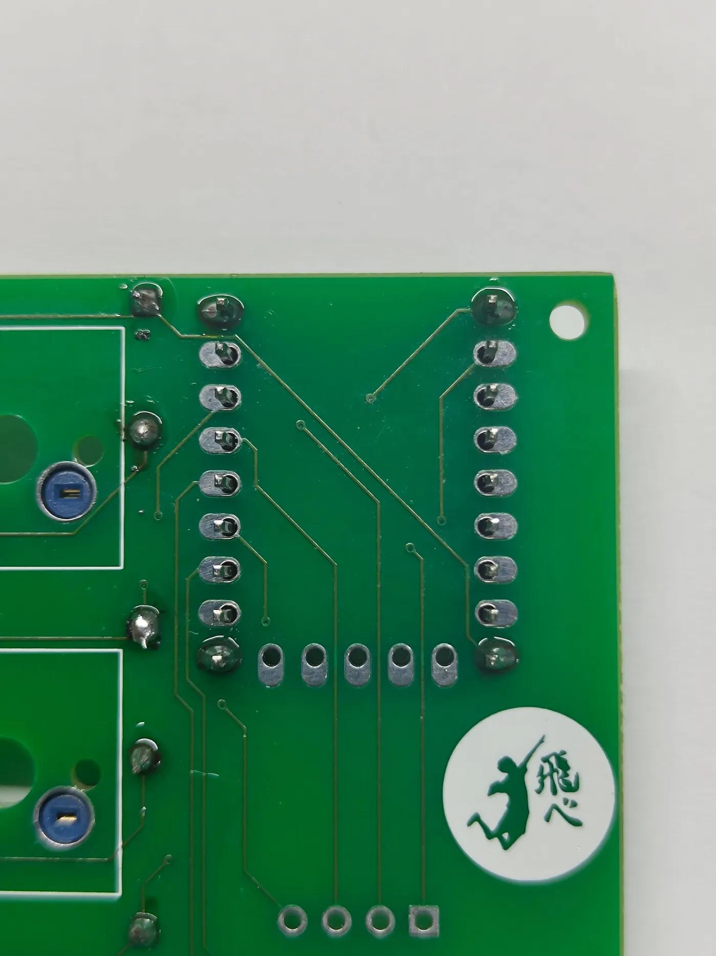
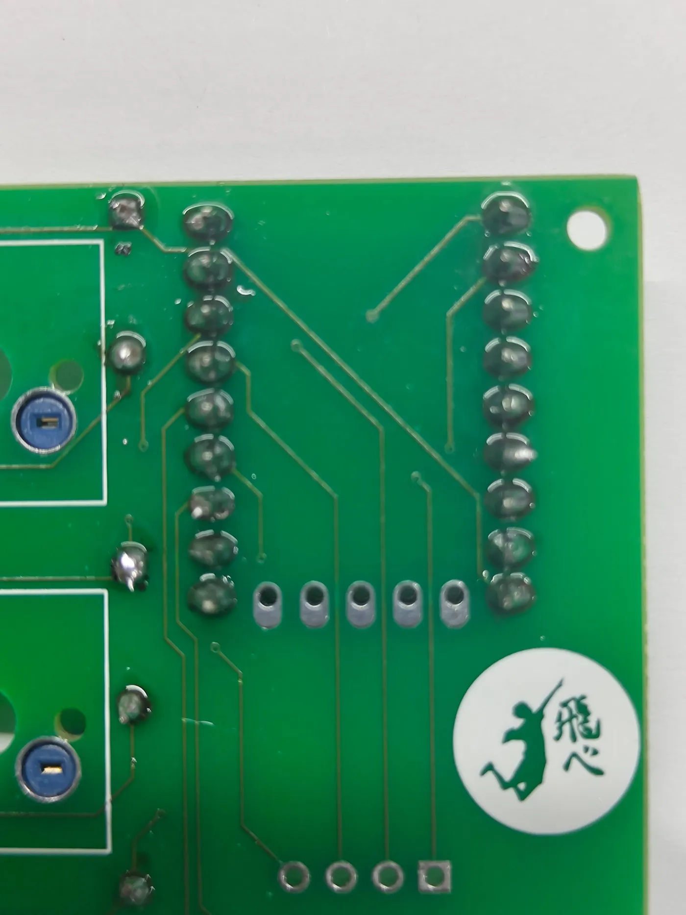
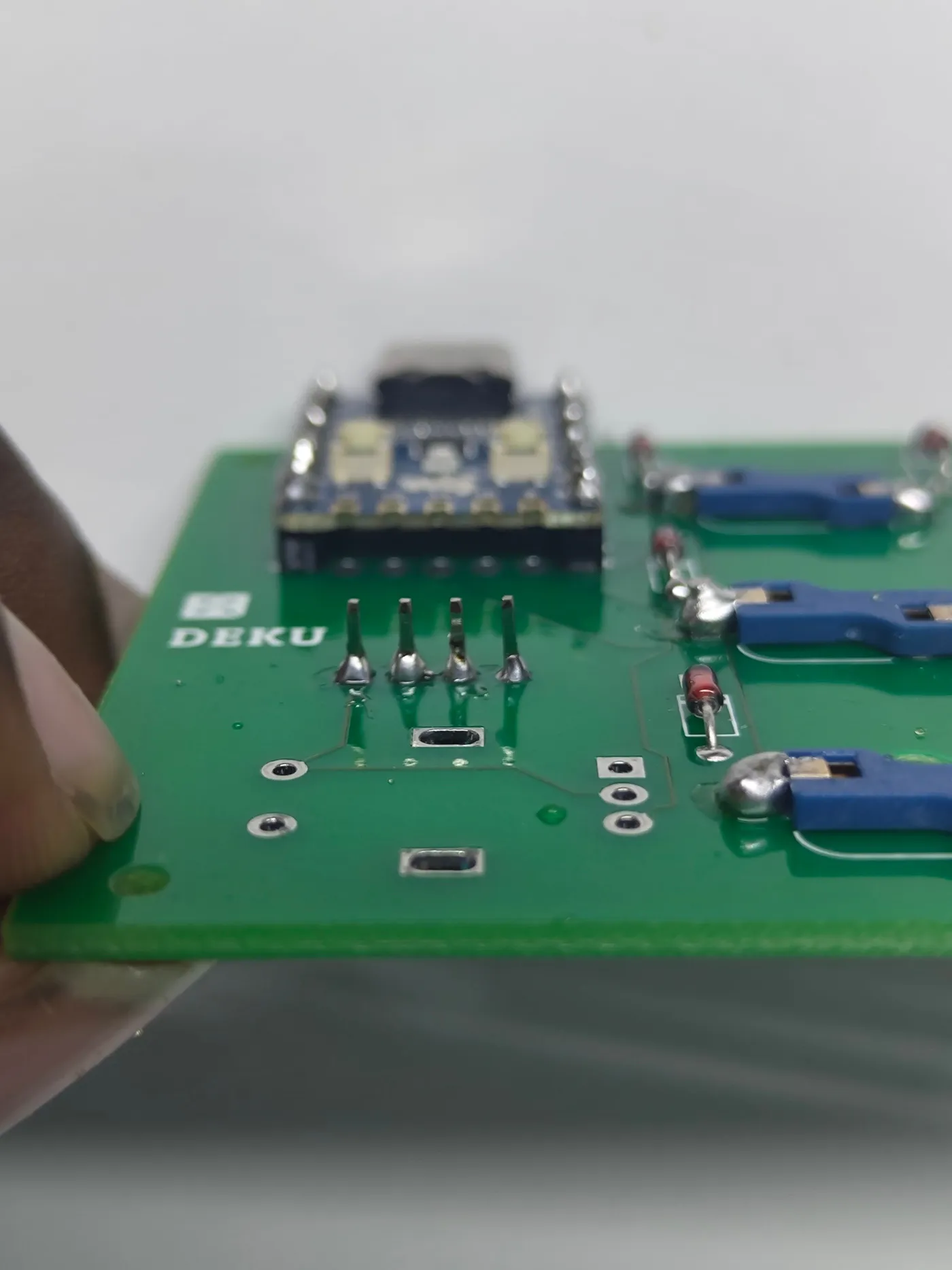
Insert header pins through the RP2040 and hold them upright using a breadboard. Solder the corner pins first to lock the angle, then solder the rest. Remove from the breadboard, insert the RP2040 into the PCB footprint on the bottom side, and solder from the top. Trim any protruding pins.
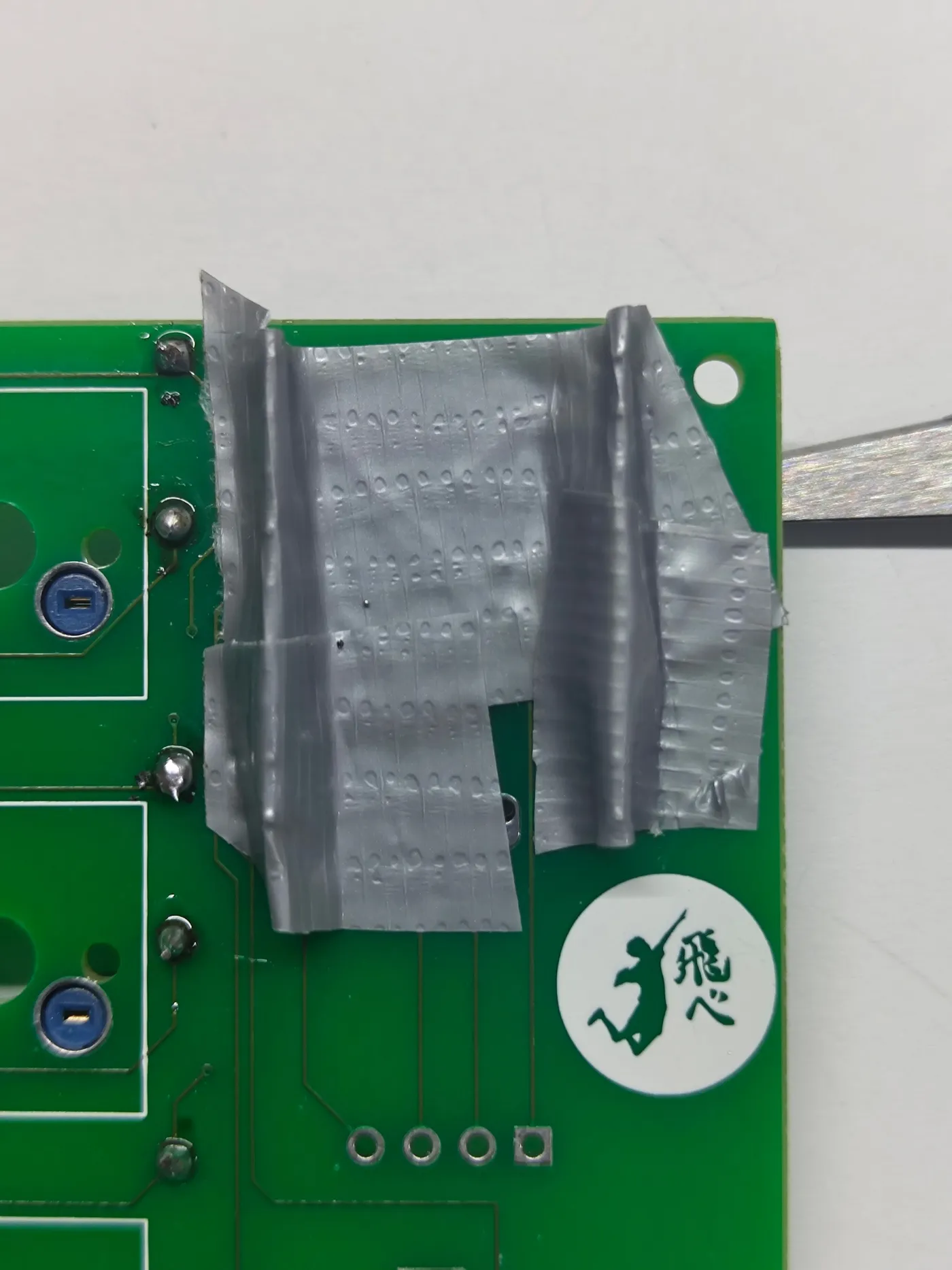
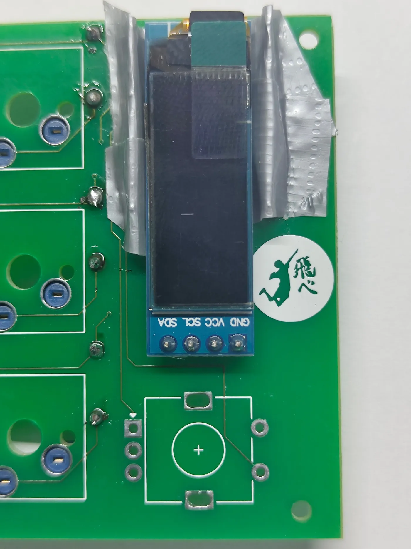
Insert the I2C OLED display into the header on the top side of the PCB. Check the orientation matches the silkscreen, then solder from the bottom. Trim the pin stubs with pliers.
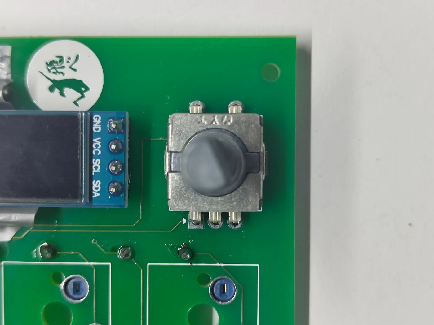
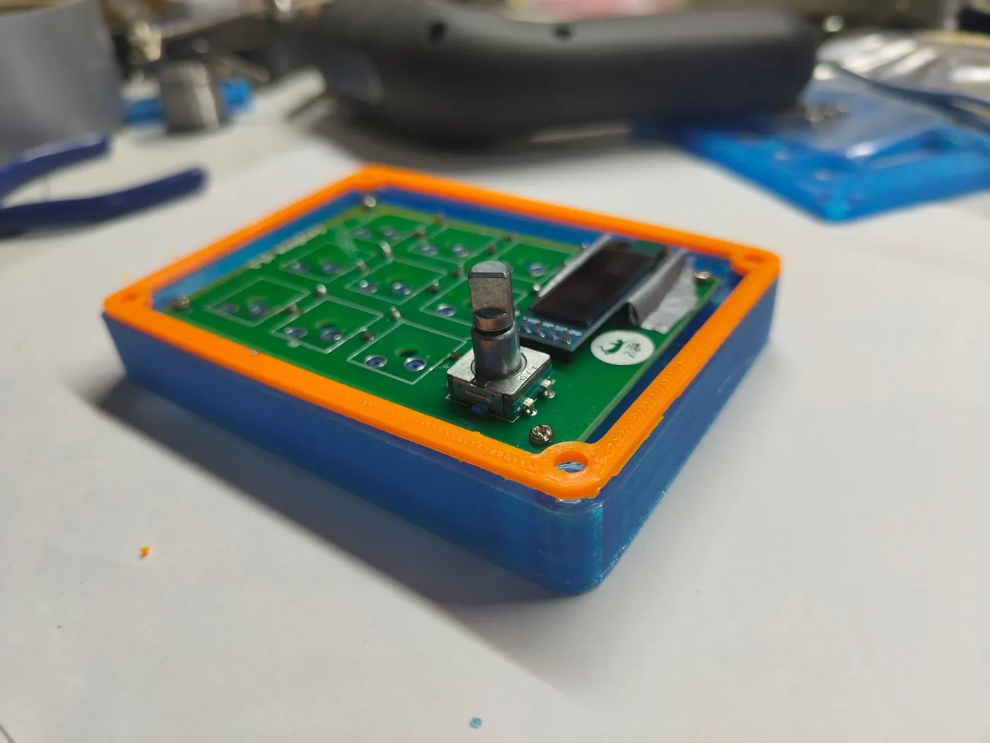
Insert the rotary encoder into the PCB in the correct orientation and solder from the bottom side.

Before assembling the case, flash QMK firmware. Hold the BOOT button on the RP2040, connect USB-C, then release. The board appears as a USB drive - drag the compiled .uf2 firmware file onto it. Alternatively, compile with QMK and use qmk flash.
Take the 3D-printed base piece. Insert the PCB with the USB-C port facing out through the cutout.
Align the PCB holes with the standoffs in the base and fasten with the M2 (small) screws.
Snap the trim piece around the PCB edge.
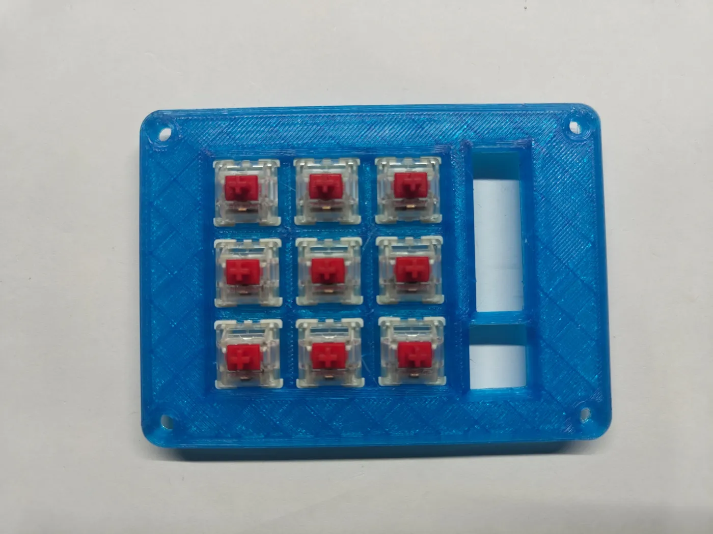
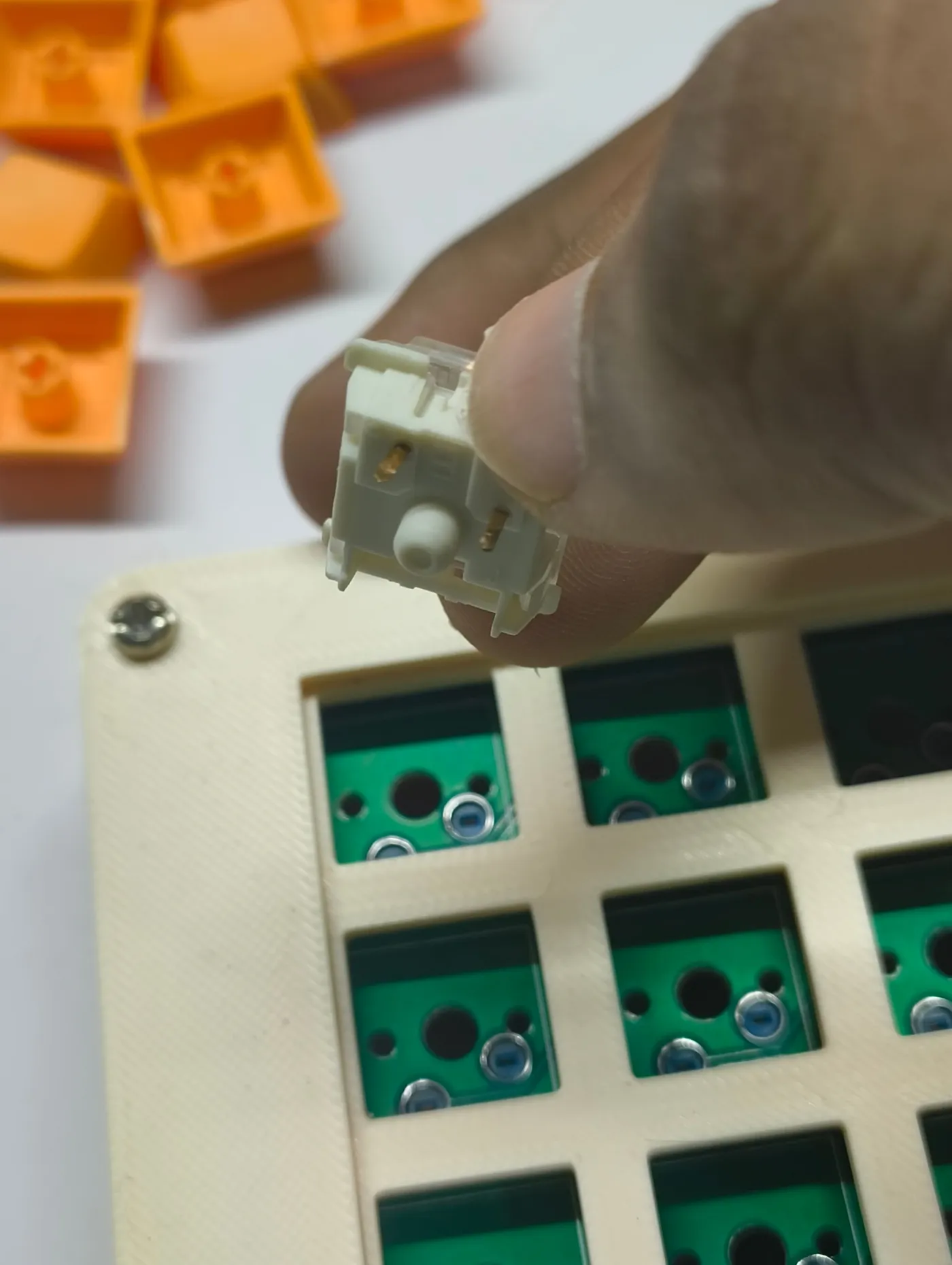
Place switches pin-side down into each hotswap socket - do not force them. Then set the top case piece on top and secure with the M2.5 (larger) screws.
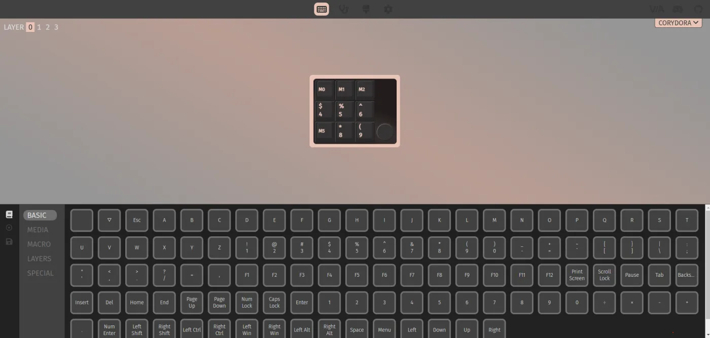
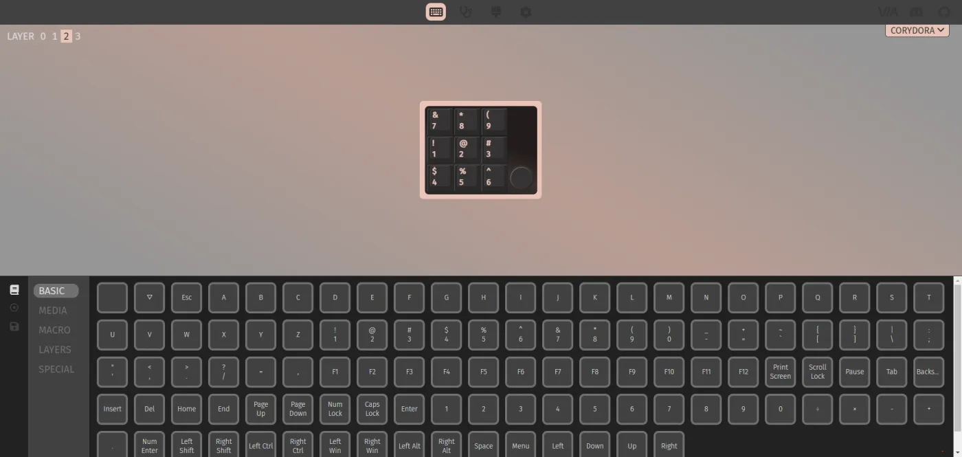
Your CoryDora ships pre-flashed and ready. This guide covers inserting switches, attaching keycaps, and remapping keys with VIA.
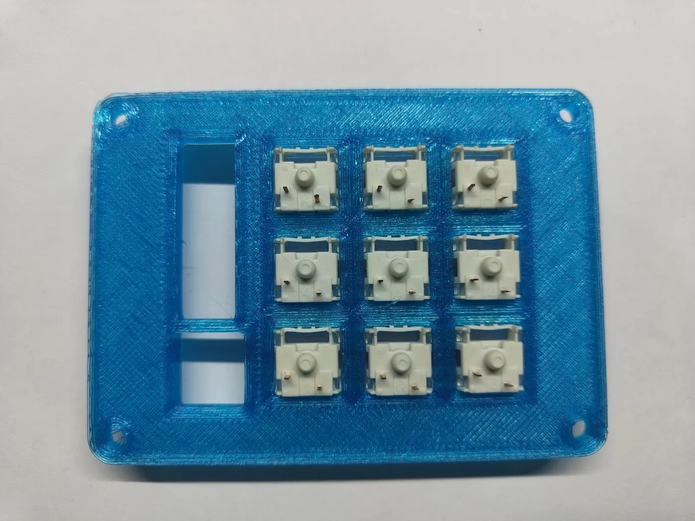
Your package contains an unpopulated CoryDora (PCB assembled, no switches), a bag of mechanical switches, and keycaps. Remove the board from its packaging.
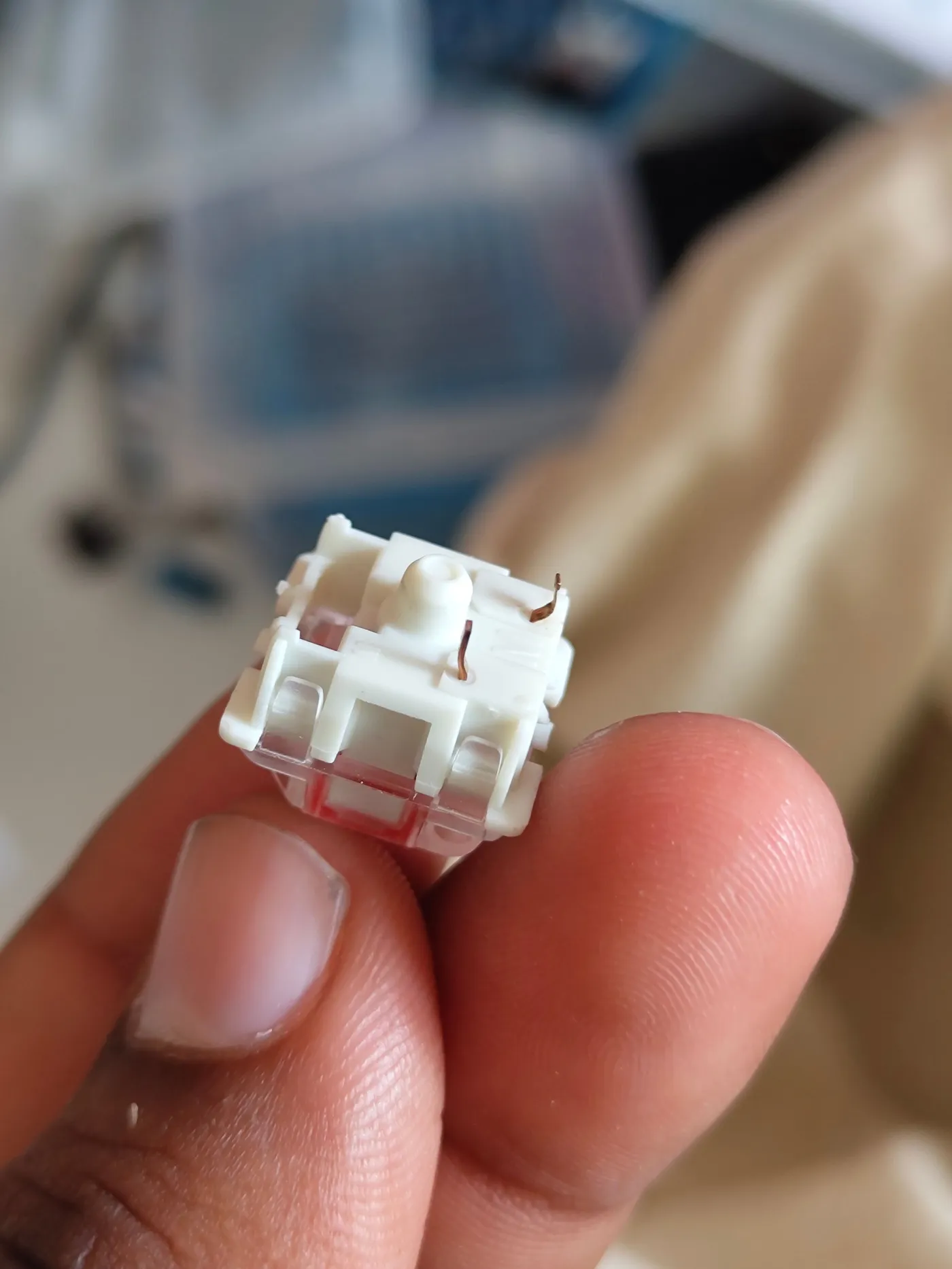
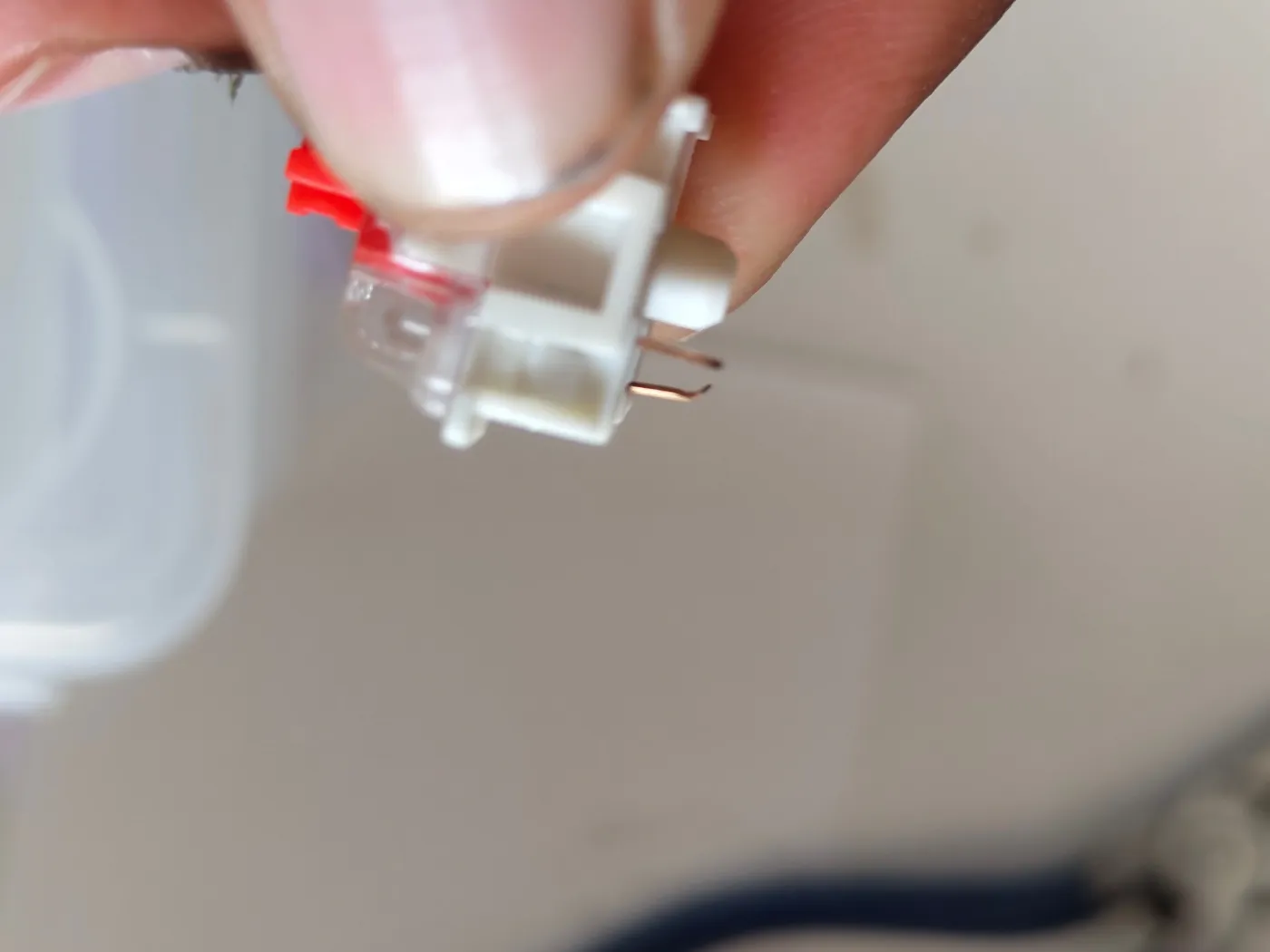
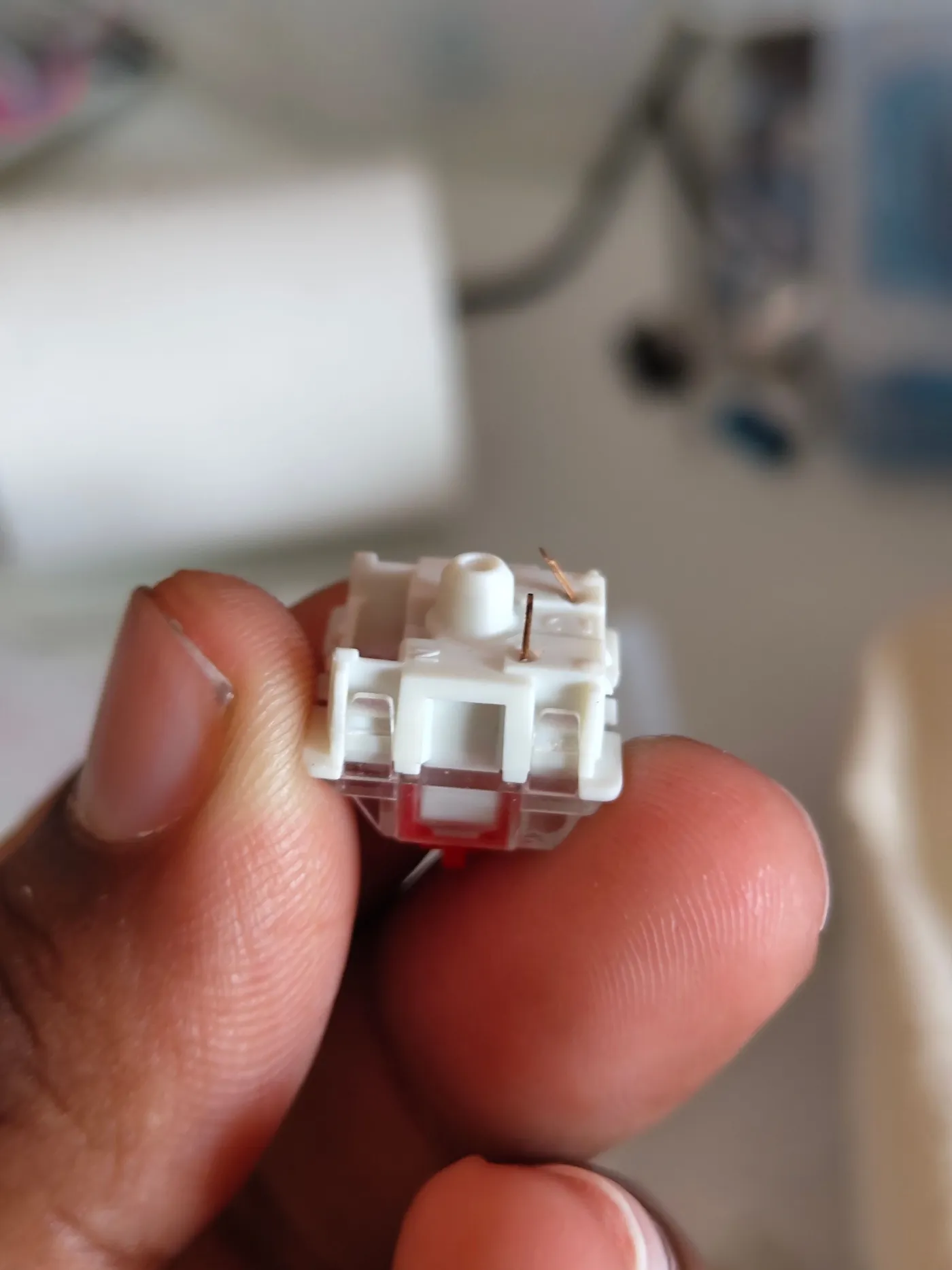
Align each switch so its two pins point down into the hotswap sockets. Press firmly and evenly until it clicks. If a pin gets bent, straighten it with tweezers before reinserting.
Press each keycap down onto its switch stem until it seats. Insert all switches first, then cap them all.
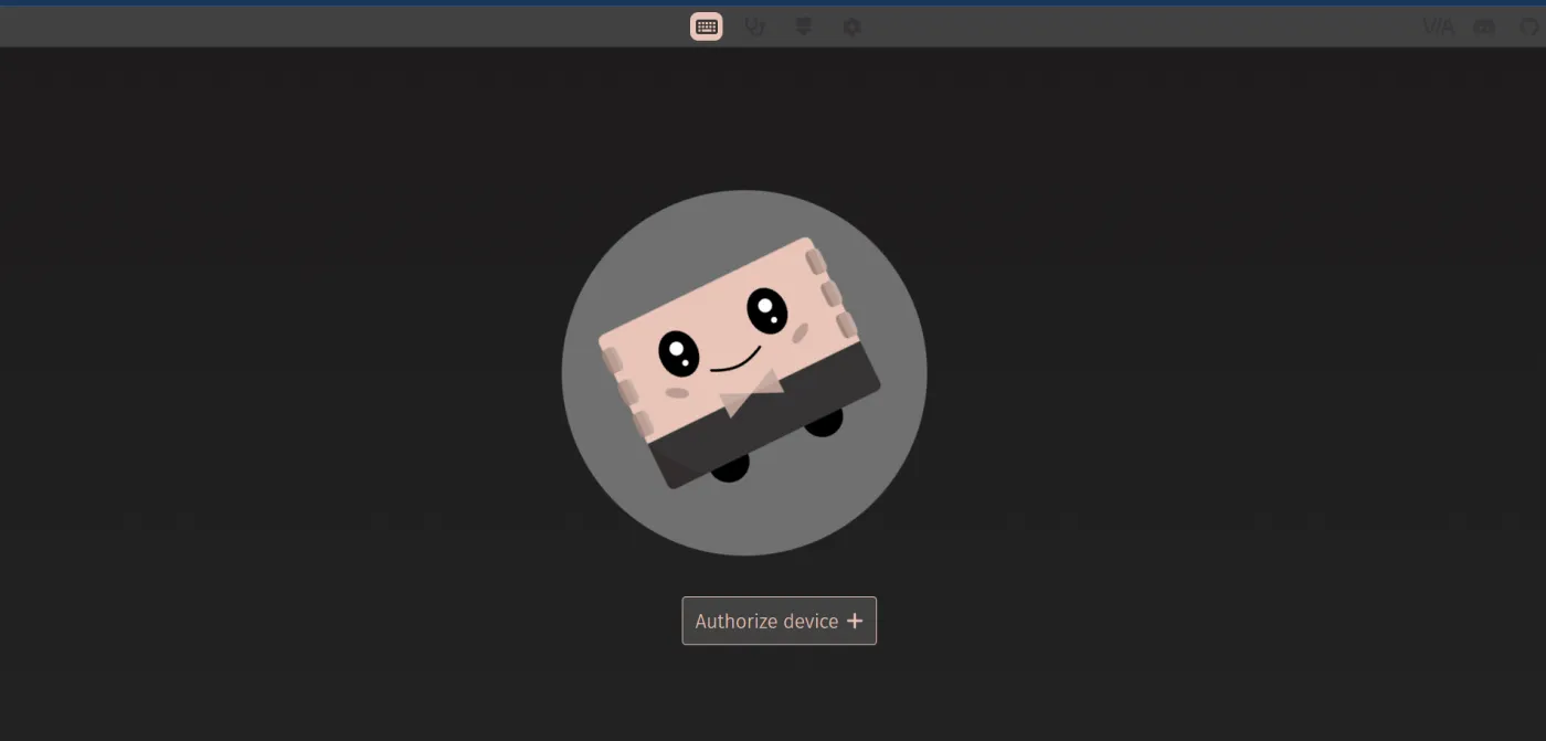
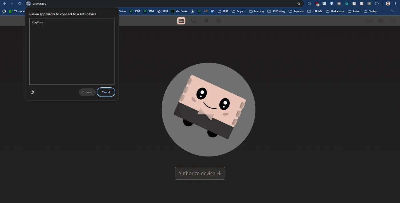
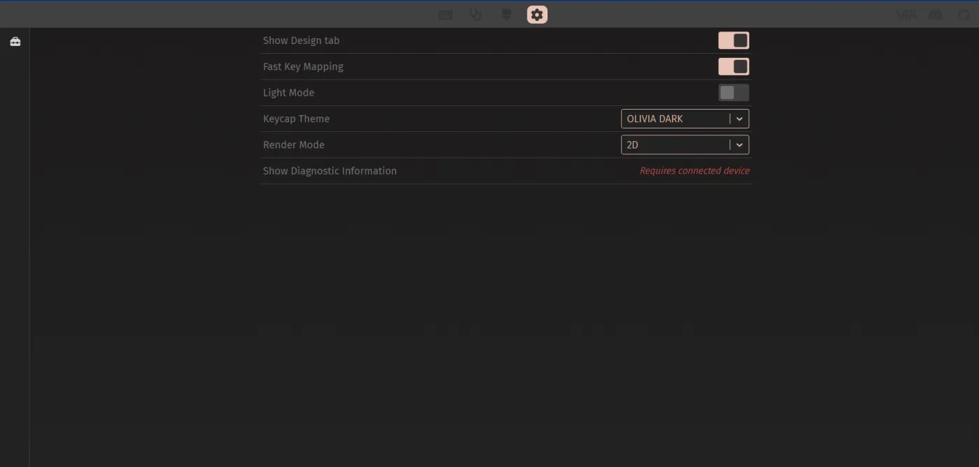
Plug CoryDora in, then visit usevia.app. Click Authorize Device and select CoryDora from the browser popup.
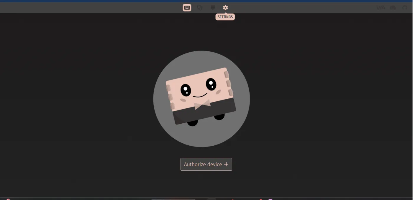
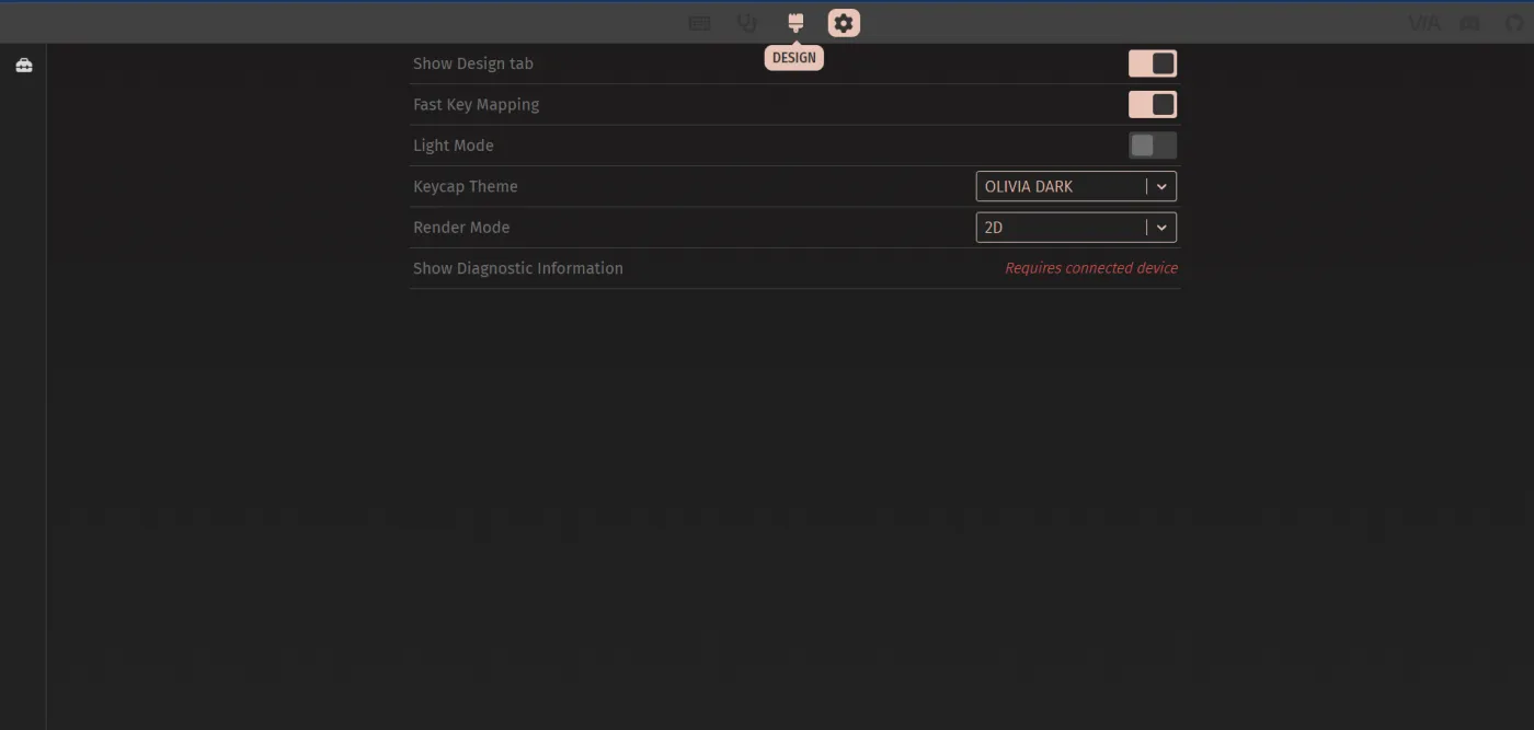
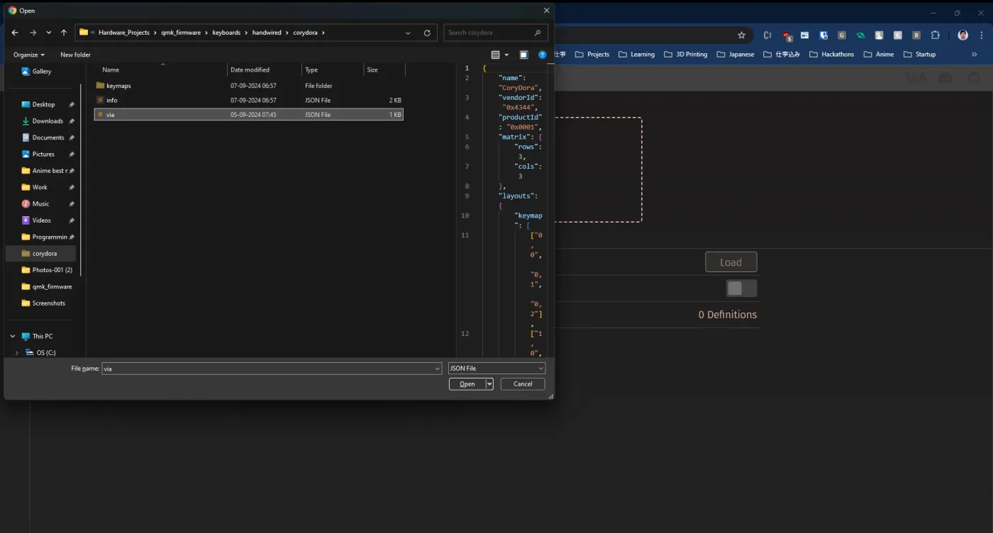
Clone the qmk_firmware repo and find keyboards/handwired/corydora/via.json. In VIA, open the Settings menu, enable Show Design Tab, then use the Load button in the Design tab to load that via.json file.
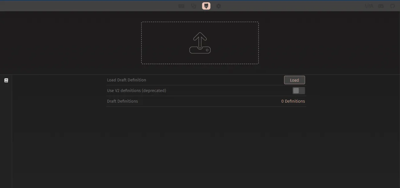
Once the definition loads, navigate to the Configure tab to drag-and-drop new keycodes onto any key. Changes apply instantly - no reflash needed.